Wrist Assembly (W1 + W2)
Builds the Left and Right wrist assemblies (stations W1 & W2). Tools: T10 Torx Allen Wrench, Blue Loctite, Needle Nose Pliers, Alcohol Pads, Wet-Erase Marker, Press or Vice, Coupler Jig. Source: Notion – Axol Assembly Instructions (migrated 2026-07-14)
 builds Wrist Assembly LeftALM-000223
Parts used
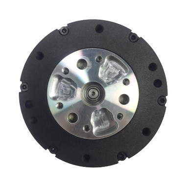 4× 24V DM-J4310-2EC V1.2
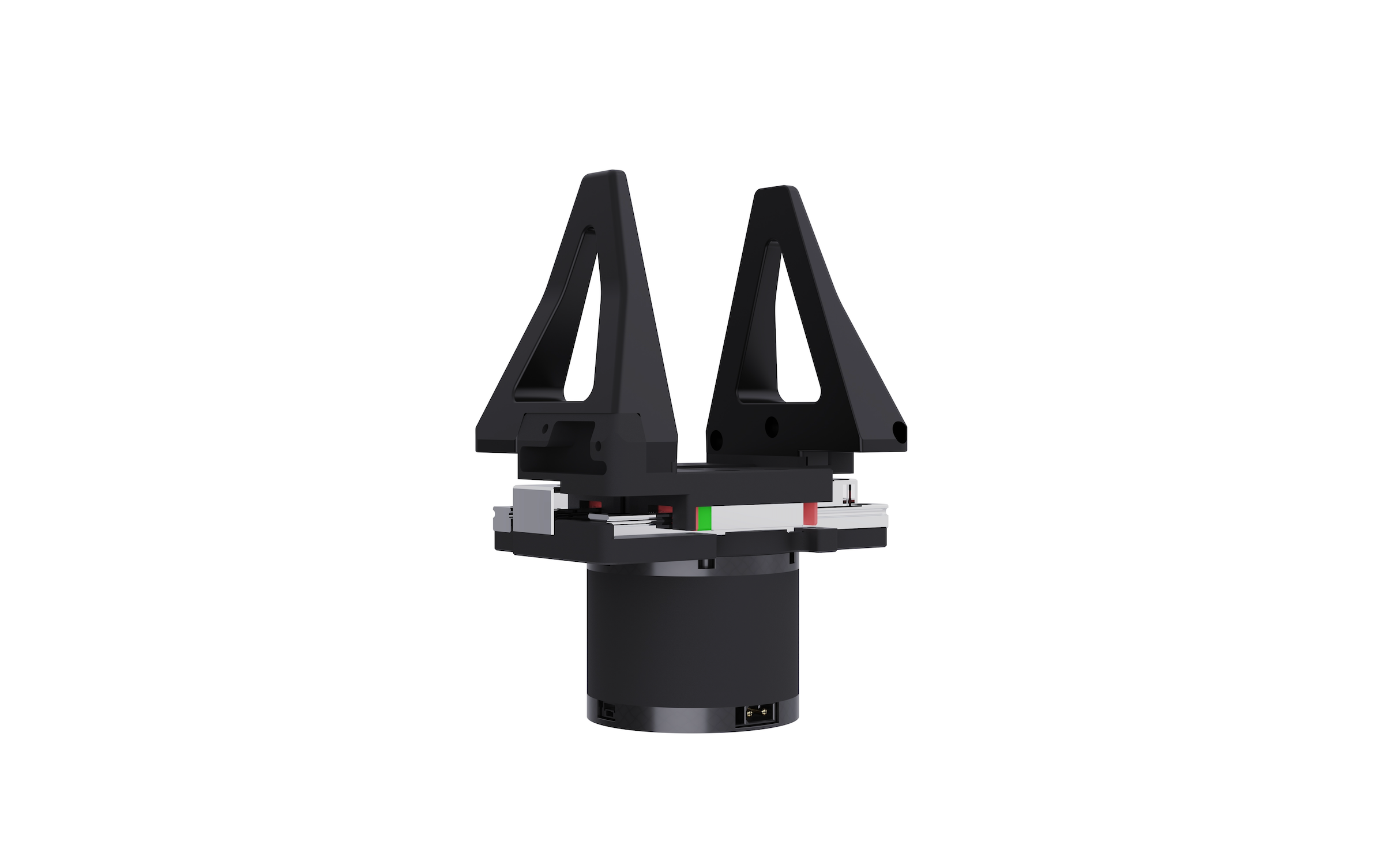 2× I2RT Gripper
 1× W1 L
 1× W1 R
 2× W1 Printed Spacer 1
 1× W1 Printed Spacer 2 L
 1× W1 Printed Spacer 2 R
 2× W2
2× W2 1× W2 Coupler
 2× W2 TPU Wire Cover
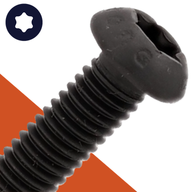 8× BH-TX-M3-08
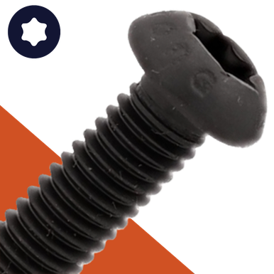 8× BH-TX-M3-10
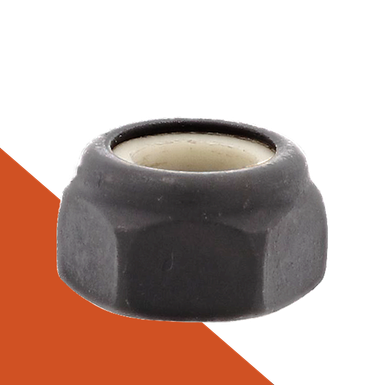 4× NNY-M3
 8× DP-R-03-06
 6× DP-R-04-12
 6× BH-TX-M3-14
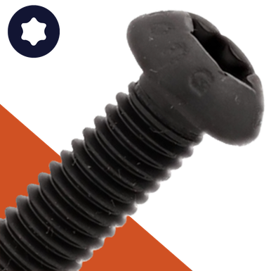 28× BH-TX-M3-06
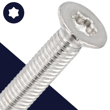 8× FH-TX-M2.5-10
 2× W -> W2 Cable
 2× W -> W3 Cable
 2× W -> EE Cable
 2× CAN Termination Board Assembly
 12× FH-TX-M3-16
Step 1
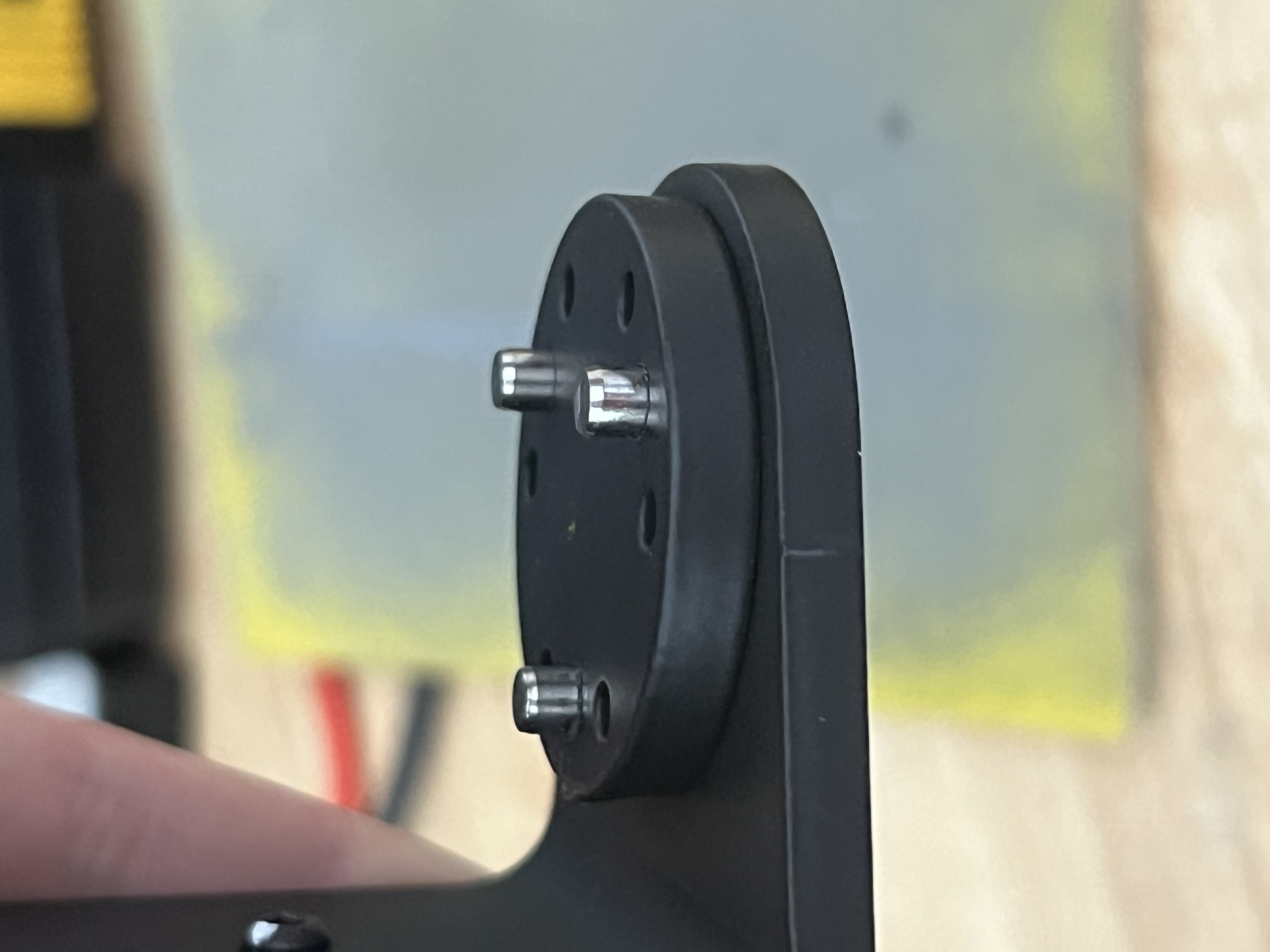
Press 6x DP-R-04-12 into 2x W2 with a TOWEL for paint protection and slide the 2x W2 Coupler on top. The coupler should be a loose fit.
edit step
Step 2
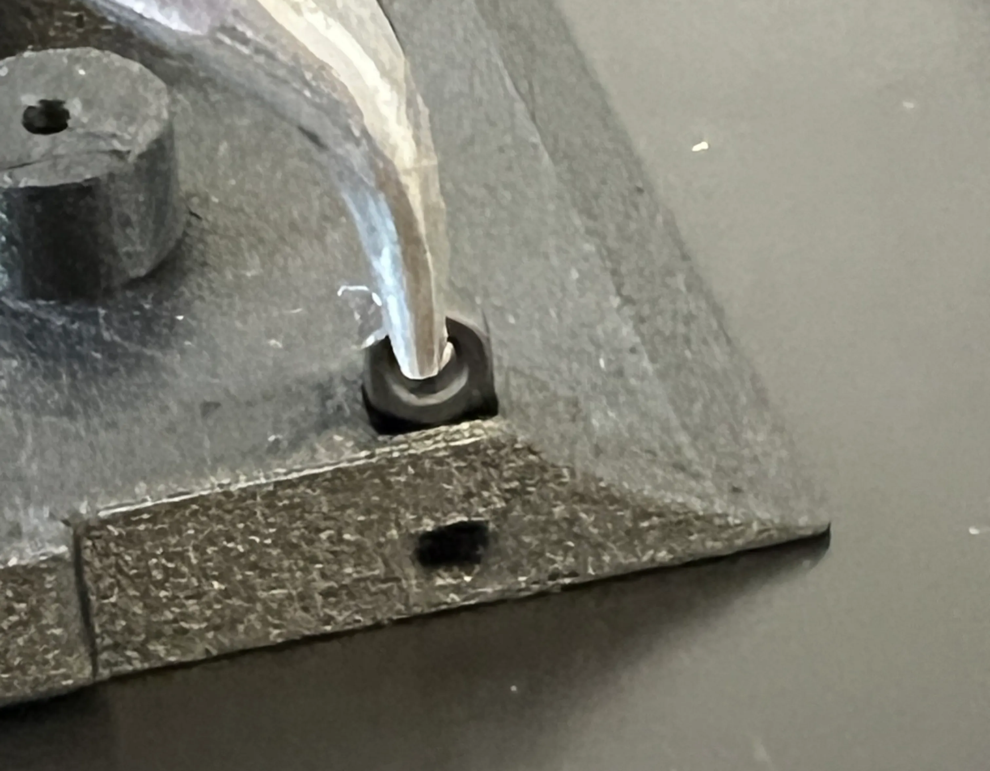
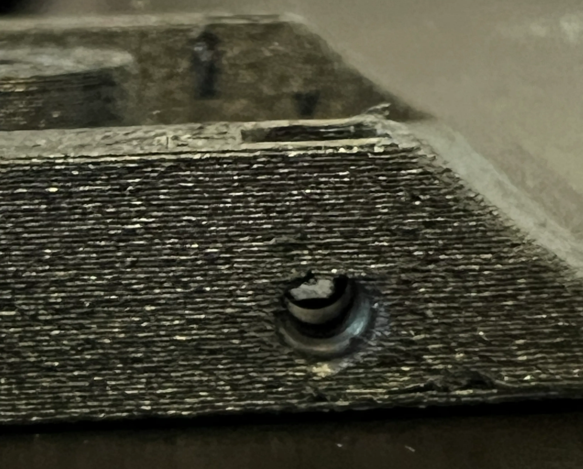
Press 4x NNY-M3 into the Left and Right W1 Spacer: the flat side of the nut faces out; press deep enough that the M3 hole is centered on the M3 nut.
edit step
Step 3
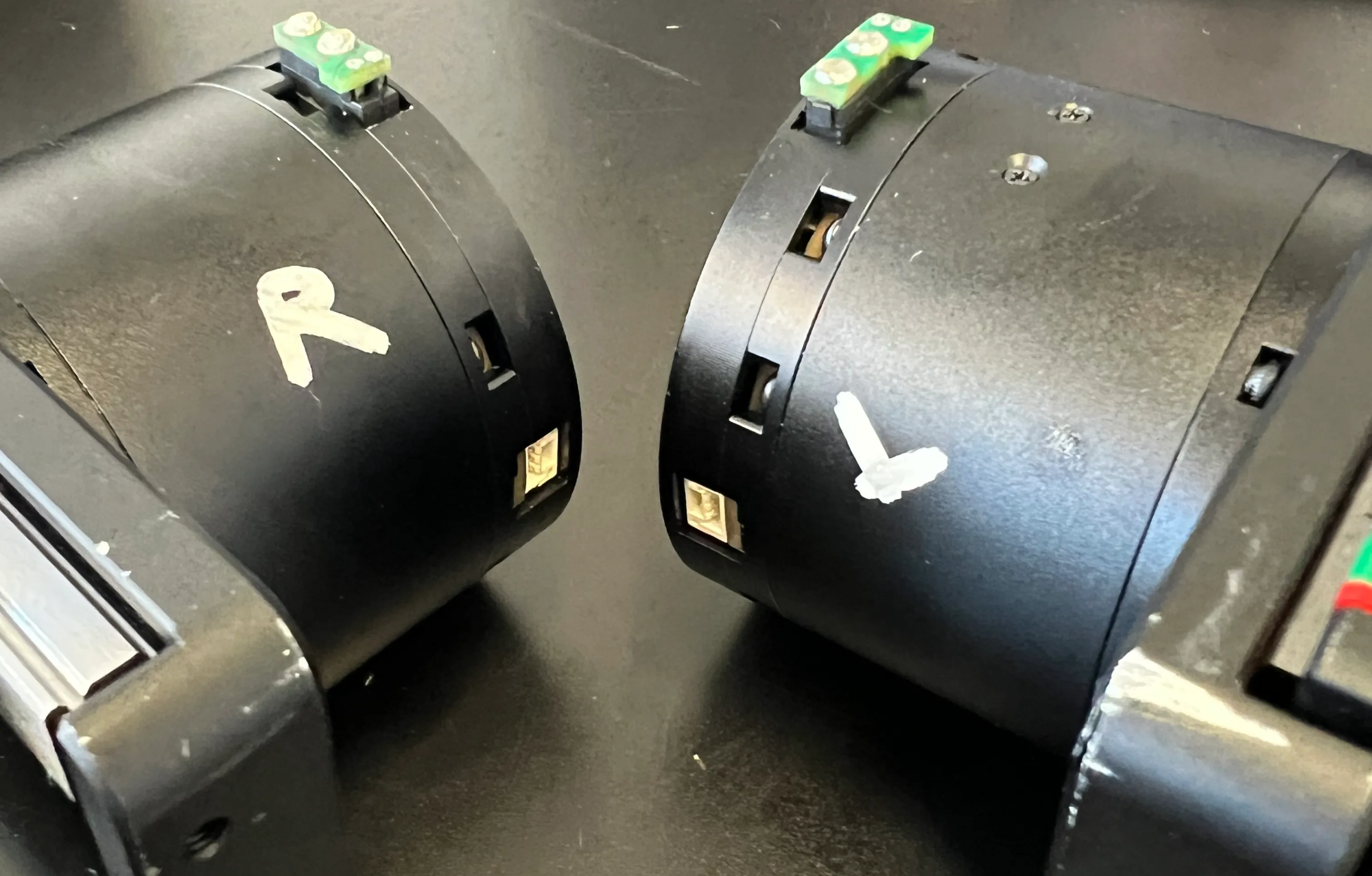
Install 2x CAN termination boards on the 2x Grippers. Note: the EtherCAT connection should face the outside — see the orientation and markings in the photo (grippers shown upside-down).
edit step
Step 4
Attach the Left and Right Gripper to 2x W2 with 8x BH-TX-M3-08 and Blue Loctite. Note: the flange on W2 should be on the opposite side of the EtherCAT port. WARNING: do not use excess Loctite — the mounting holes on the back of the gripper are open to the circuit board.
edit step
Step 5
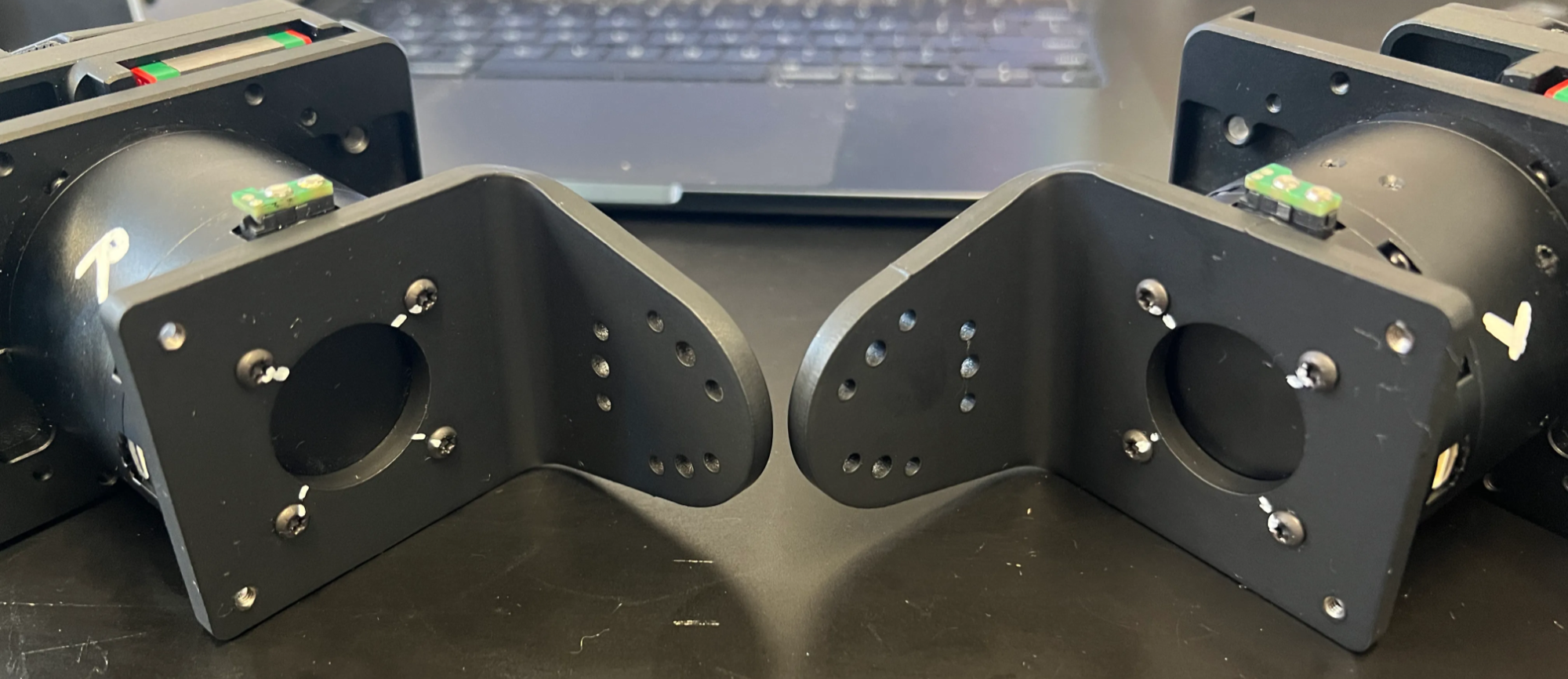
Install 2x CAN termination boards on the 2x Grippers. Note: the EtherCAT connection should face the outside — see the orientation and markings in the photo (grippers shown upside-down).
edit step
Step 6
Attach the Left and Right Gripper to 2x W2 with 8x BH-TX-M3-08 and Blue Loctite. Note: the flange on W2 should be on the opposite side of the EtherCAT port. WARNING: do not use excess Loctite — the mounting holes on the back of the gripper are open to the circuit board.
edit step
Step 7
Wipe & mark the 8x BH-TX-M3-08 bolts on the Left and Right Gripper with an Alcohol Pad to remove any Blue Loctite, then mark with a Wet-Erase Marker.
edit step
Step 8
Attach 2x Yaw DM-J4310's to 2x W1's with 12x BH-TX-M3-06 and Blue Loctite. Remove the stickers from the motors.
edit step
Step 9
Fish 2x XT-30+2 Cables from the 2x Yaw DM-J4310's through 2x W1's pitch opening.
edit step
Step 10
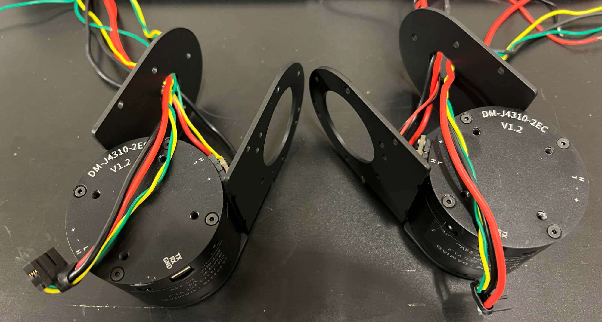
Attach 2x Yaw DM-J4310's to 2x W1's with 12x BH-TX-M3-06 and Blue Loctite. Remove the stickers from the motors.
edit step
Step 11
Fish 2x XT-30+2 Cables from the 2x Pitch DM-J4310's through 2x W1's pitch opening.
edit step
Step 12
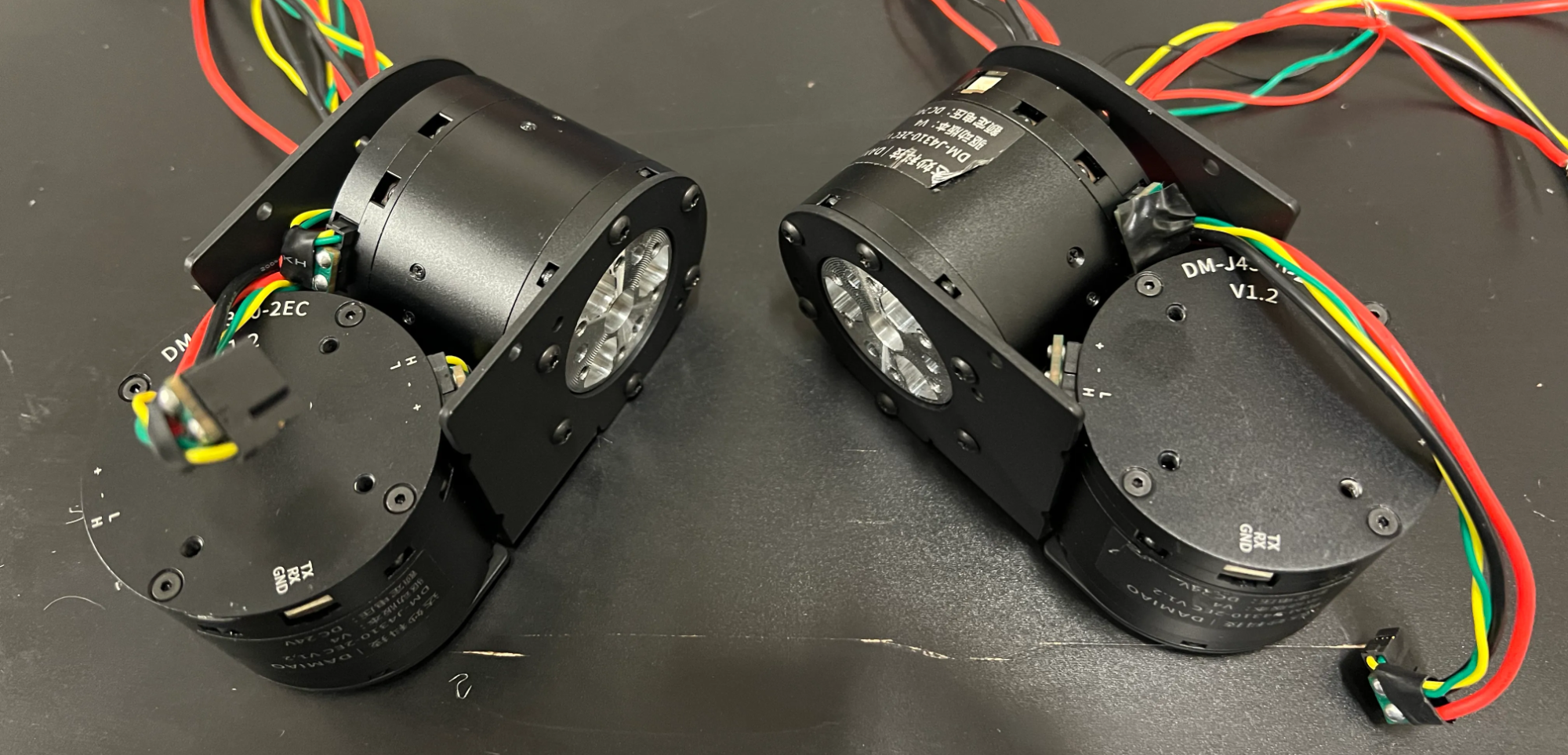
Attach 2x Pitch DM-J4310's to 2x W1's with 12x BH-TX-M3-06 and Blue Loctite.
edit step
Step 13
Install 2x W1 Printed Spacer 1 with 6x BH-TX-M3-14 to the Left and Right Assemblies.
edit step
Step 14
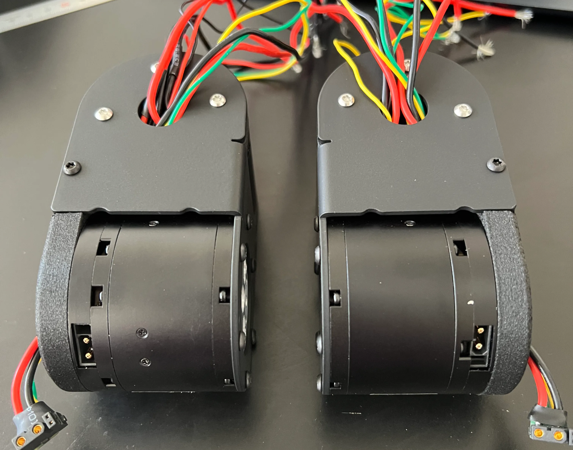
Install W1 Printed Spacer 2 L & W1 Printed Spacer 2 R with 8x BH-TX-M3-10 to the motors and 2x BH-TX-M3-06 on the sides.
edit step
Step 15
Install 2x W1 Printed Spacer 1 with 6x BH-TX-M3-14 to the Left and Right Assemblies.
edit step
Step 16
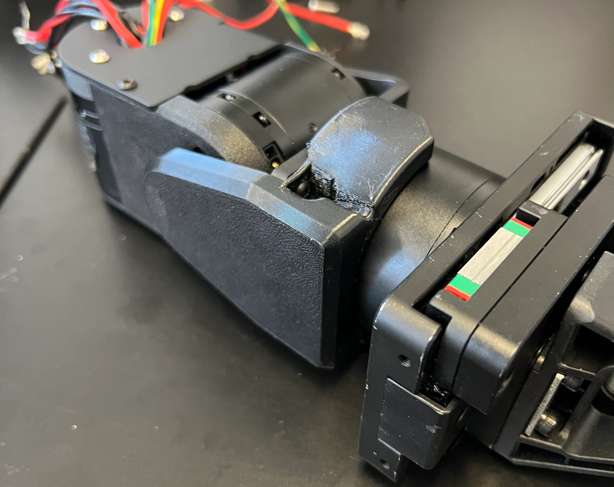
Install W1 Printed Spacer 2 L & W1 Printed Spacer 2 R with 8x BH-TX-M3-10 to the motors and 2x BH-TX-M3-06 on the sides.
edit step
Step 17
Wipe the assembly with an Alcohol Pad to remove any Loctite before it cures.
edit step
Step 18
Attach 2x W2 TPU Wire Cover to the Left and Right Assemblies with 4x BH-TX-M3-06.
edit step
Step 19
Wipe the assembly with an Alcohol Pad to remove any Loctite before it cures.
edit step
+ Add step
Quality checklist
- The dowel pins are flush
- The gripper is marked L or R
- The flat side of the M3 Nuts face out
- The wrist does not get stuck during full ROM
- The wrist does not squeak during full ROM
- The two wrist motors are touching (wires are not caught in between them)
- The XT30 connectors are not touching the motor shells
- There are 3 sets of XT30 wires coming out of the hole
- All fasteners are marked with wet-erase marker
- All fasteners are loctited
- No paint damage
- W1 Spacer is flat and flush
- CAN IDs set for all parts of the wrist
- Continuity checked for all CAN and power