Forearm Assembly (W0 + E2)
Builds the Left and Right forearm assemblies (stations W0 + E2). Tools: CA Glue, T20 Torx Allen Wrench, T10 Torx Allen Wrench, White Liquid Chalk Marker, RTV162 glue, Wire Strippers. Quantities below are per arm unless stated. Source: Notion – Axol Assembly Instructions (migrated 2026-07-14)
 builds Forearm Assembly LeftALM-000225
Parts used
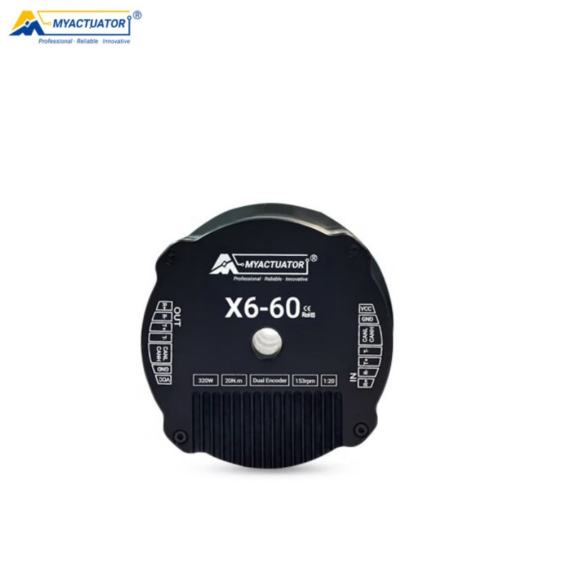 2× RMD-X6-60 Motor
 2× S3/E2 Endstop Coupler 3.175mm
 1× X6 Endstop Tab (4 pack)
 2× E2 Thick Plate
 2× E2 Chassis 1
 2× E2 Chassis 2
 2× E2 TPU Cover Flat
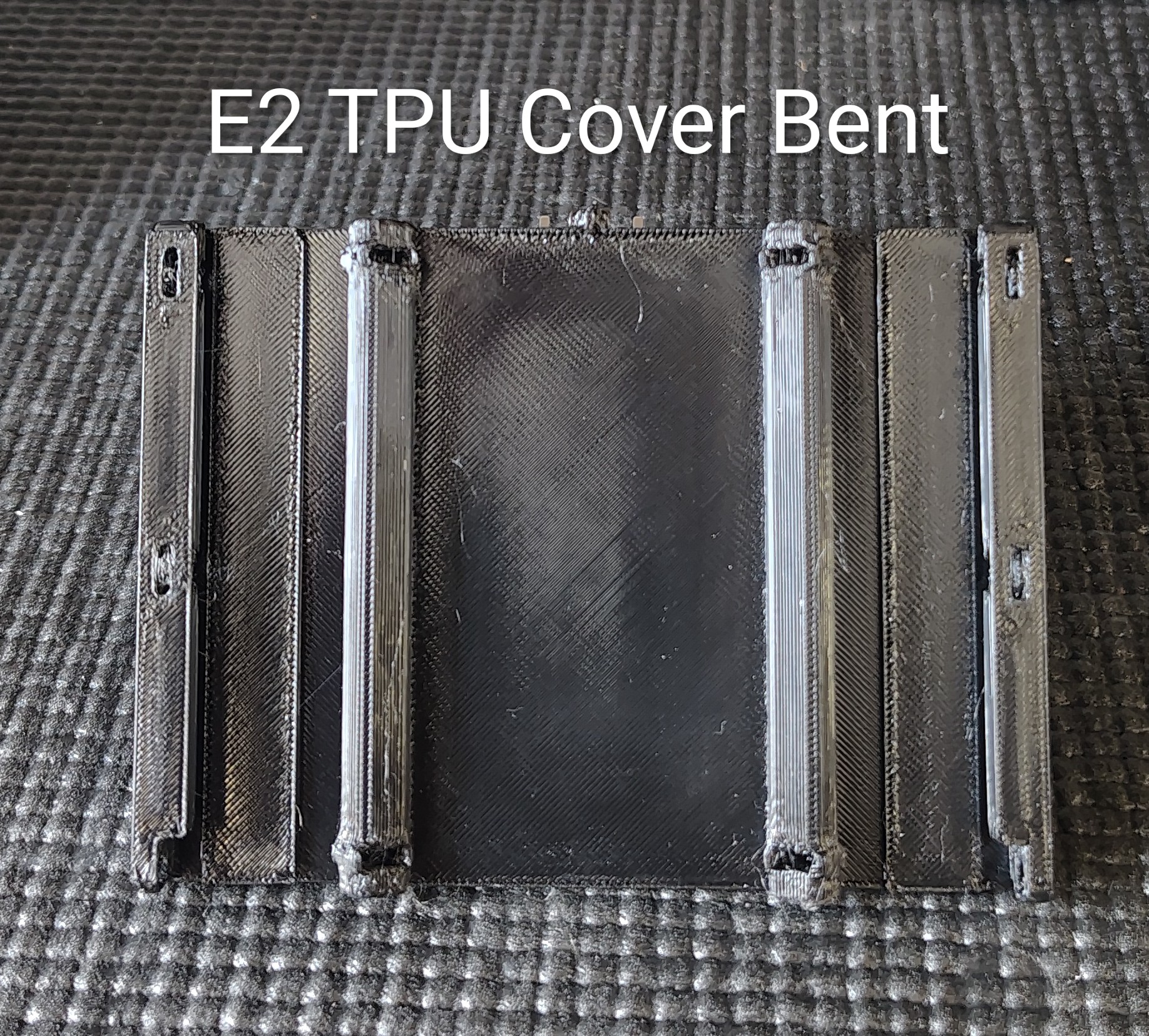 2× E2 TPU Cover Bent
 2× W0 Thick
 2× W0 Bracket 1
 2× W0 Bracket 2 (w/ Camera Connector)
 2× W0 TPU Inner Cover
 2× GMSL Holder Female
 2× W1 Coupler
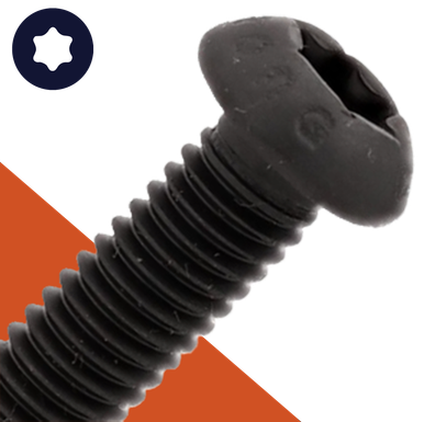 50× BH-TX-M3-08
 8× BH-TX-M3-12
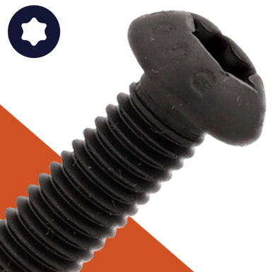 8× BH-TX-M3-16
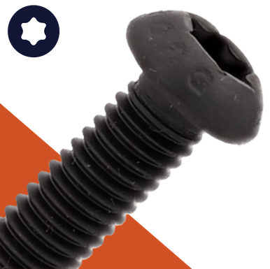 24× BH-TX-M4-10
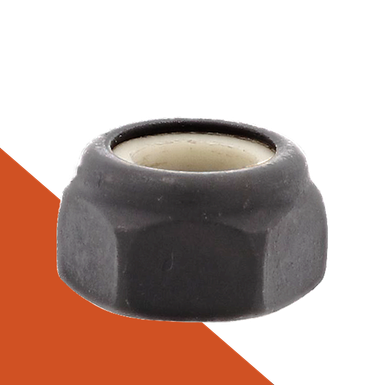 4× NNY-M3
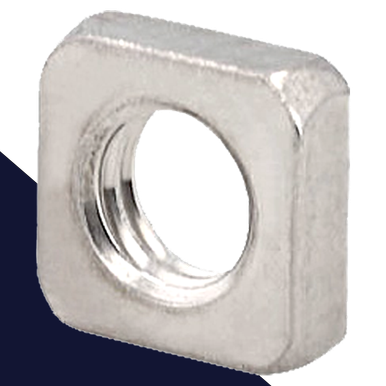 36× NSQ-M3
 6× DP-R-04-12
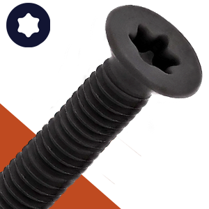 6× FH-TX-M3-12
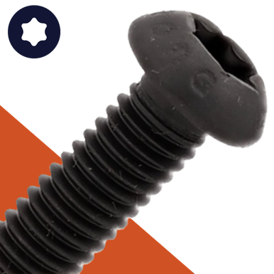 12× BH-TX-M4-08
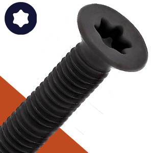 10× FH-TX-M3-08
 2× E -> W1 Cable
 2× W1 -> W2/W3/EE Cable
 8× Wago 221-415
Step 1
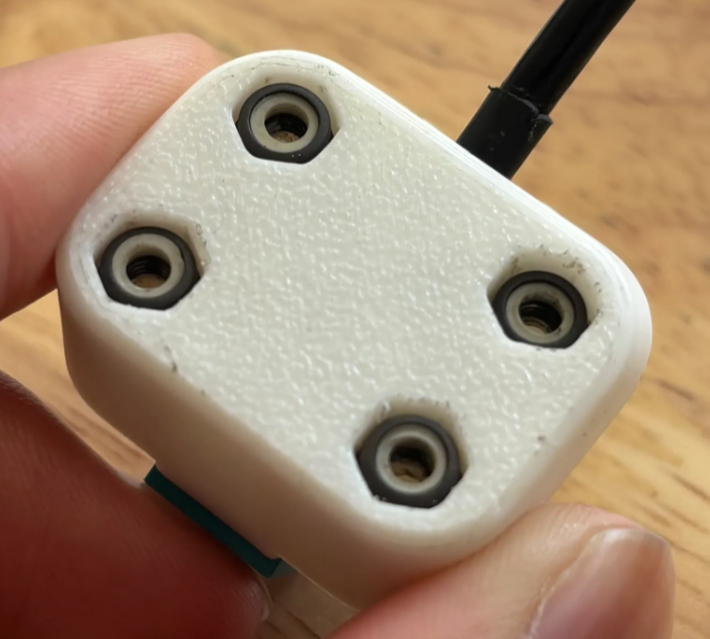
Press 4x NNY-M3 into the GMSL housing.
edit step
Step 2
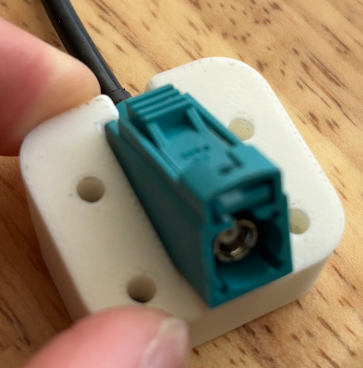
Apply CA glue into the female GMSL Housing and insert the female side of 1x M-F GMSL cable — hold for 20 seconds.
edit step
Step 3
Remove the male GMSL housing from the cable.
edit step
Step 4
Install 1x W1 → W2, W3, G Cable and 1x E → W1 Cable. Either port is fine. Make sure the XT30 connector is fully seated in the receptacle, then apply RTV162 glue. Gently heat the RTV162 glue with a heat gun to slightly solidify it.
edit step
Step 5
Route the 1x W1 → W2, W3, G Cable through the motor shaft: CAN first, then PWR + GND.
edit step
Step 6
Press 1x E2 Chassis 1 and 1x E2 Chassis 2 onto 1x RMD-X6-60 motor. The 1x E → W1 Cable needs to be closer to the E2 thick mount.
edit step
Step 7
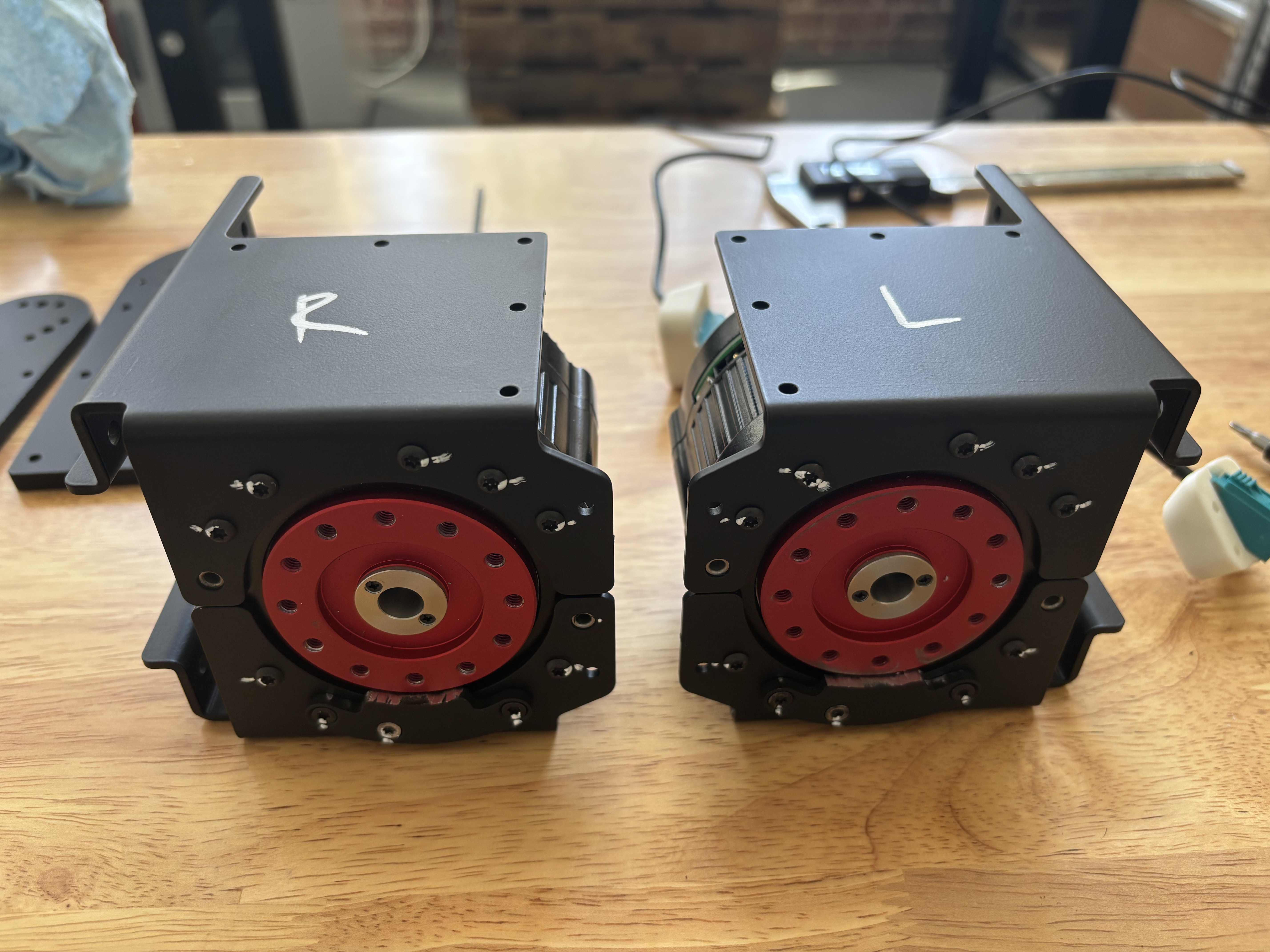
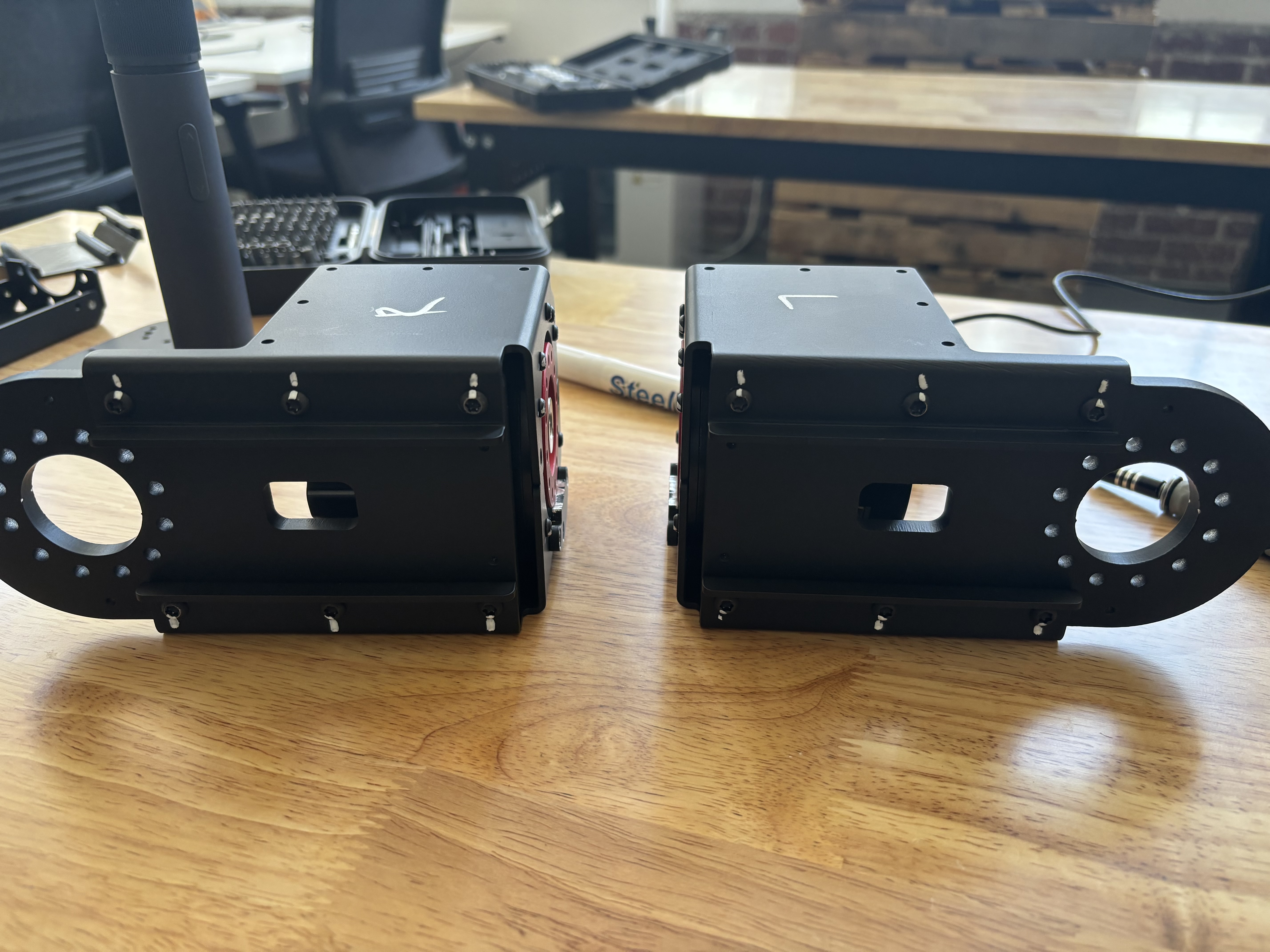
Note the LEFT and RIGHT difference for end stop installation.
edit step
Step 8
Fasten with Loctite: 7x BH-TX-M3-08 without end stop and 3x FH-TX-M3-12 with end stop. Mark screws with white chalk.
edit step
Step 9
Fasten with Loctite: 6x BH-TX-M4-08 between E2 Thick and E2 Chassis 1 & 2. Mark screws with white chalk.
edit step
Step 10
Route 1x E → W1 Cable & GMSL cable through the E2 thick cable opening (just the bottom one).
edit step
Step 11
Place the E2 end stop over the motor shaft and route the GMSL cable through the motor shaft.
edit step
Step 12
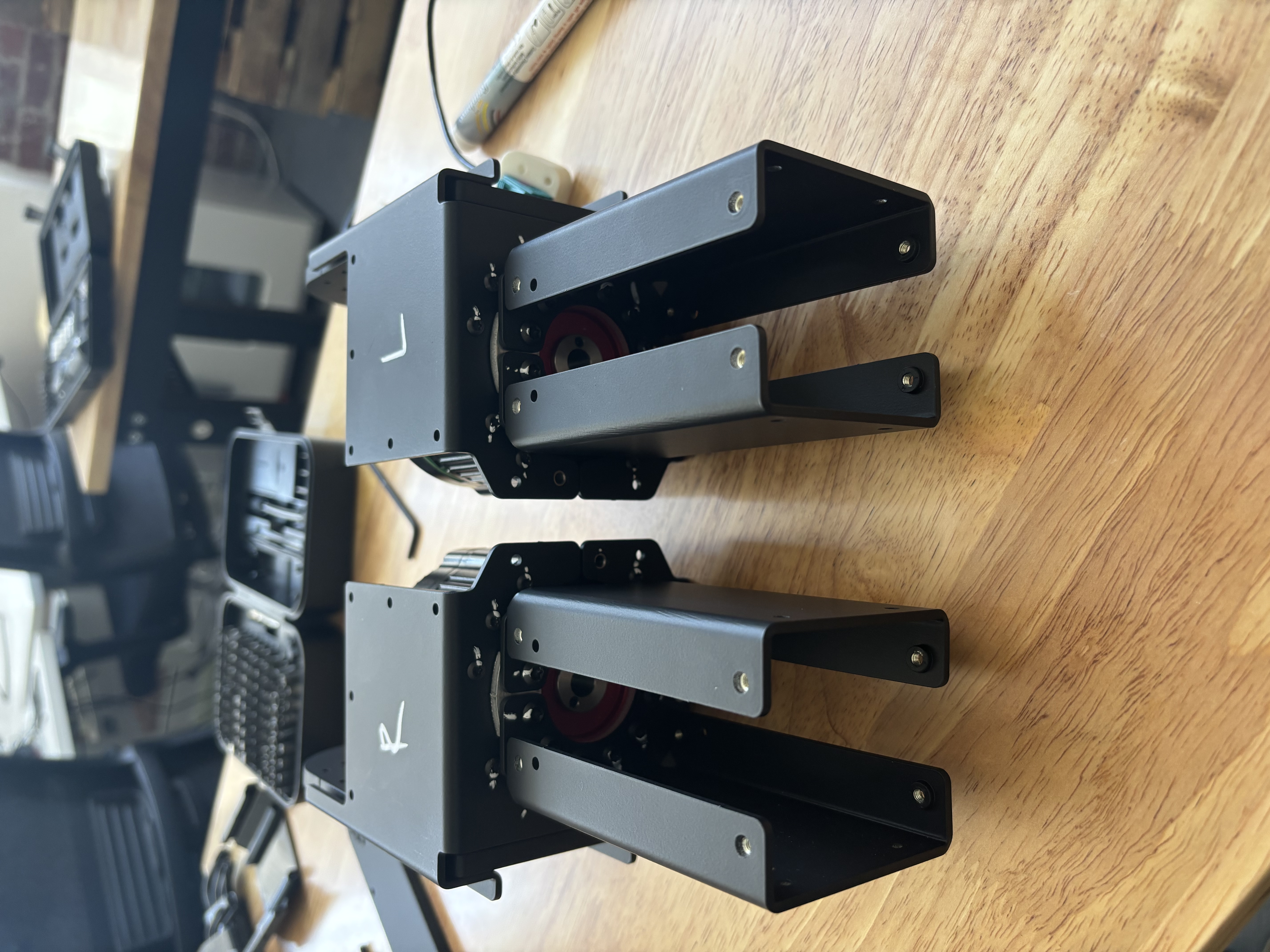
Fasten with Loctite: 12x BH-TX-M4-10 between the X6 motor shaft, E2 end stop, and W0 Bracket 1 & 2. The end stop should be opposite the X6 endstop tab. Mark screws with white chalk.
edit step
Step 13
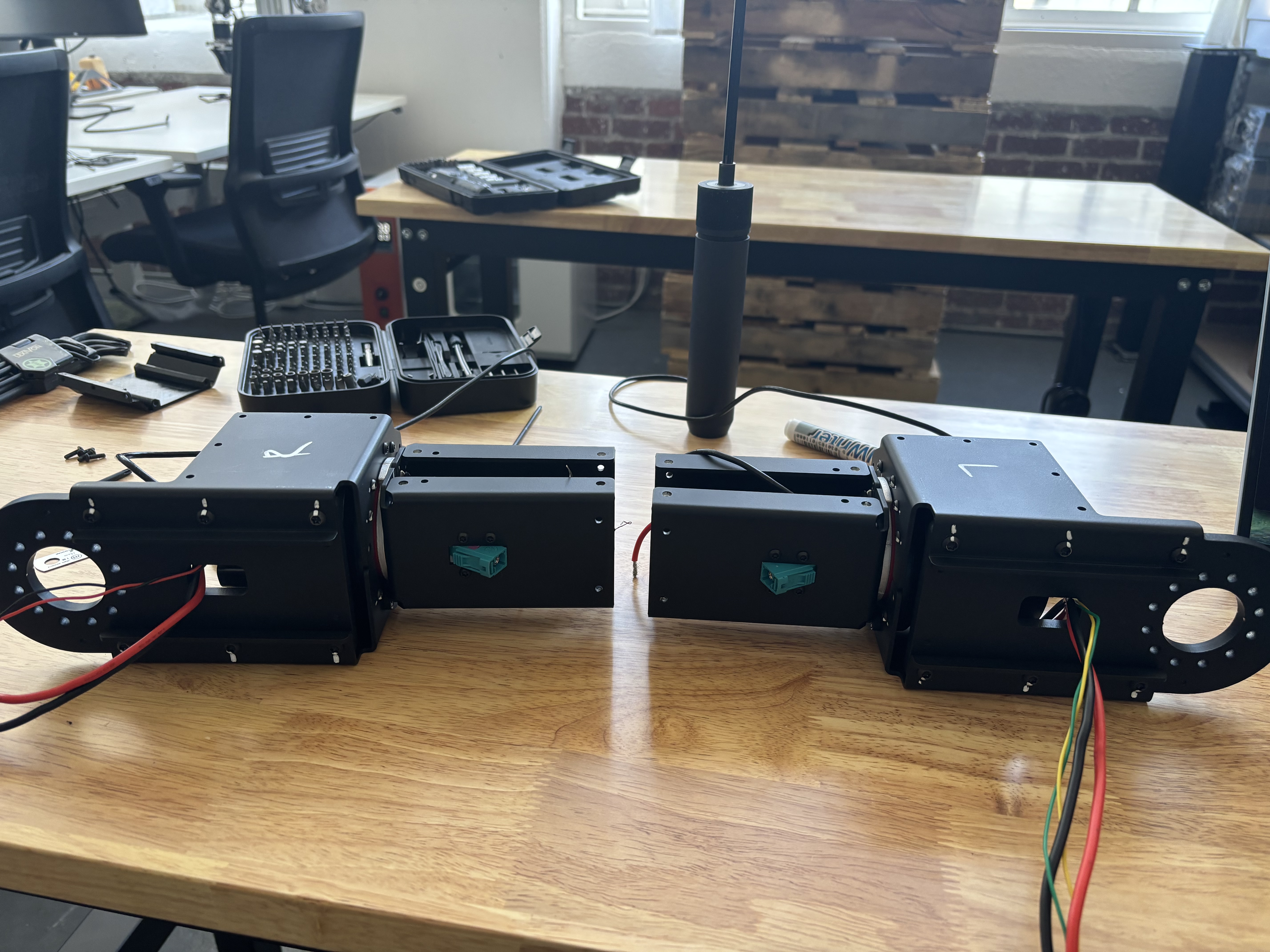
Fasten the GMSL housing with 4x BH-TX-M3-16 (no Loctite).
edit step
Step 14
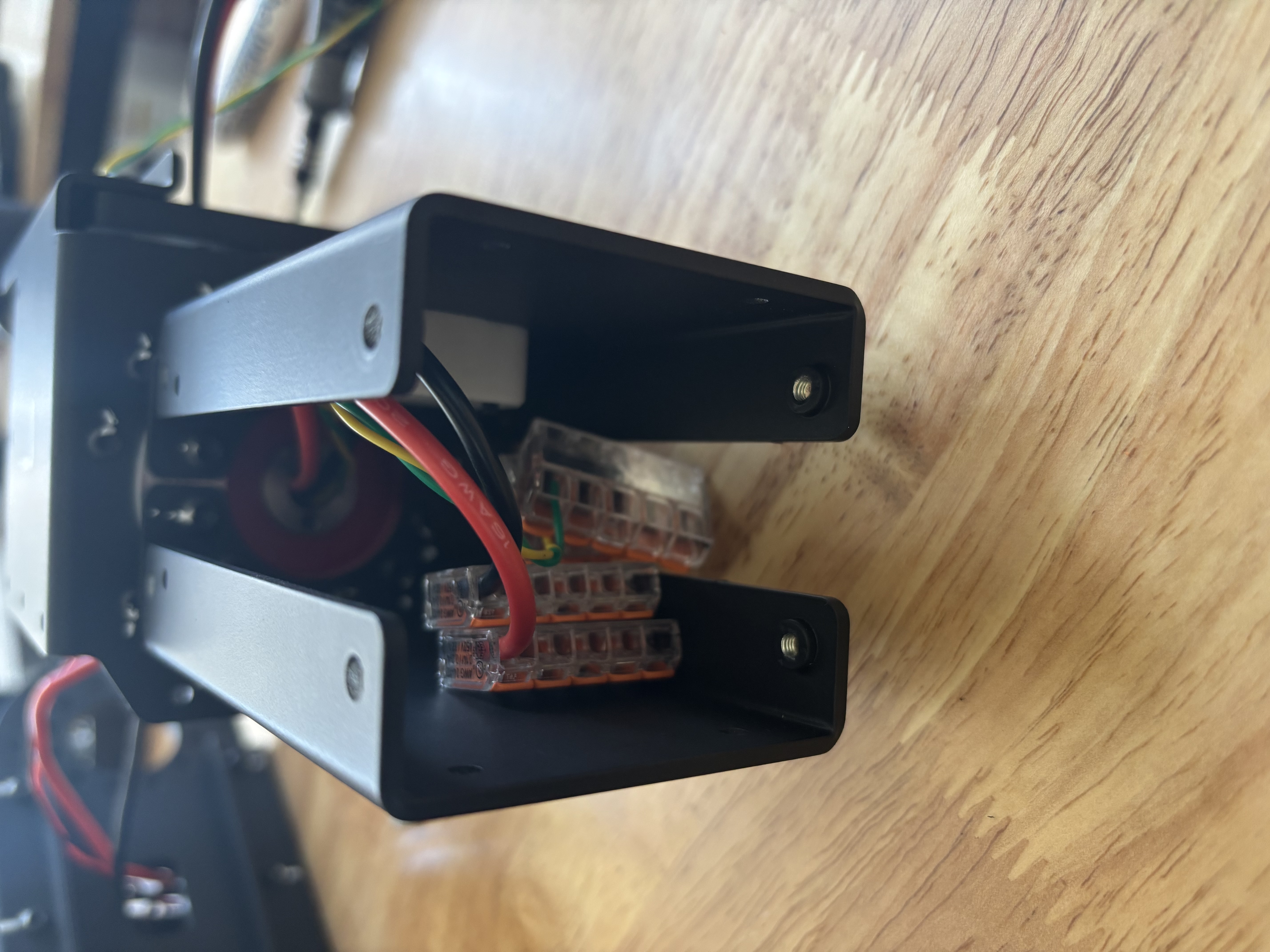
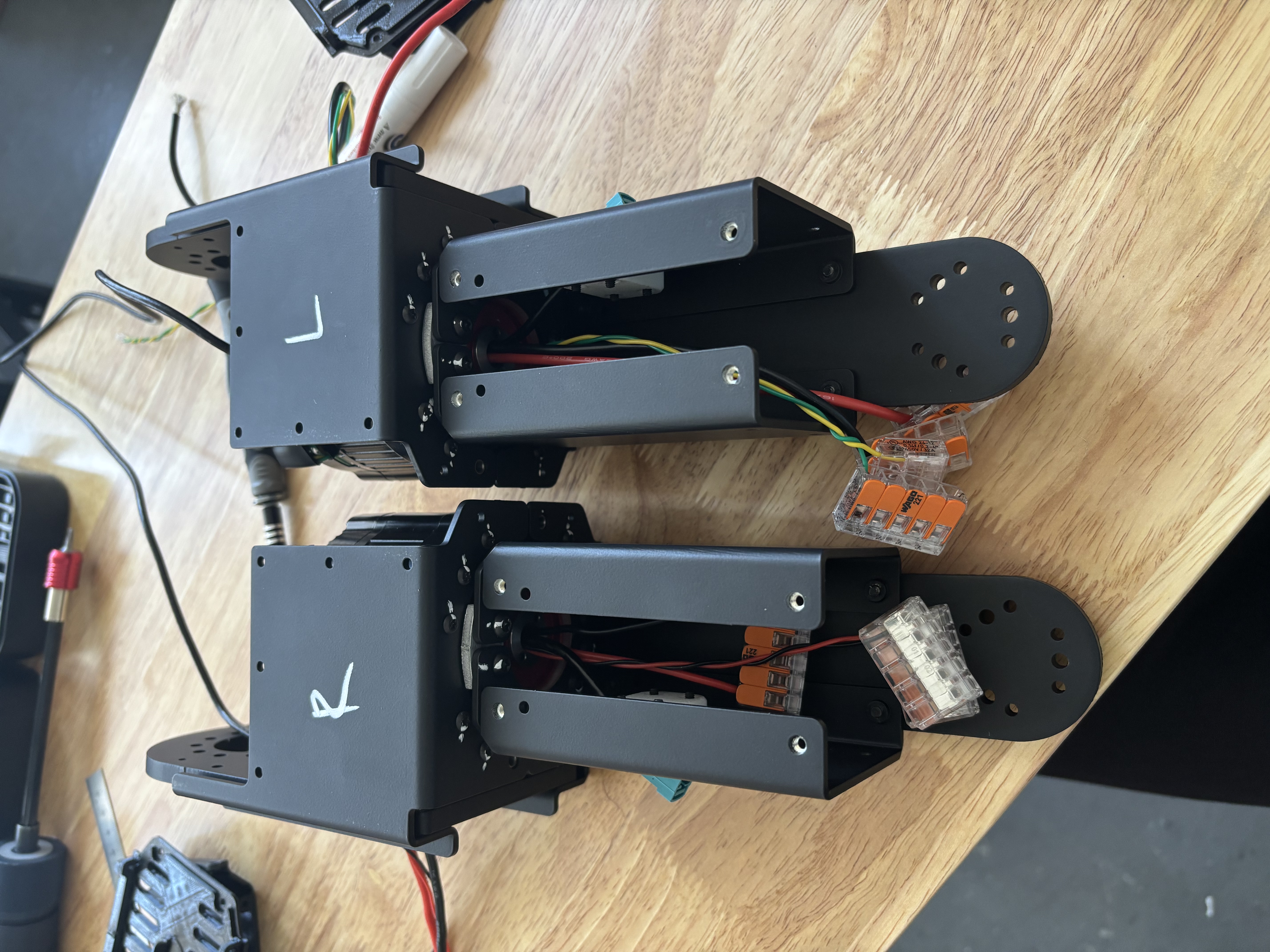
Strip wires & install the 4x Wago 221-415.
edit step
Step 15
Insert 3x DP-R-04-12 into W0 Thick and 1x W1 3.175 Coupler.
edit step
Step 16
Fasten with Loctite: W0 Thick to W0 Bracket 1 & 2 with 8x BH-TX-M3-12. Mark screws with white chalk.
edit step
Step 17
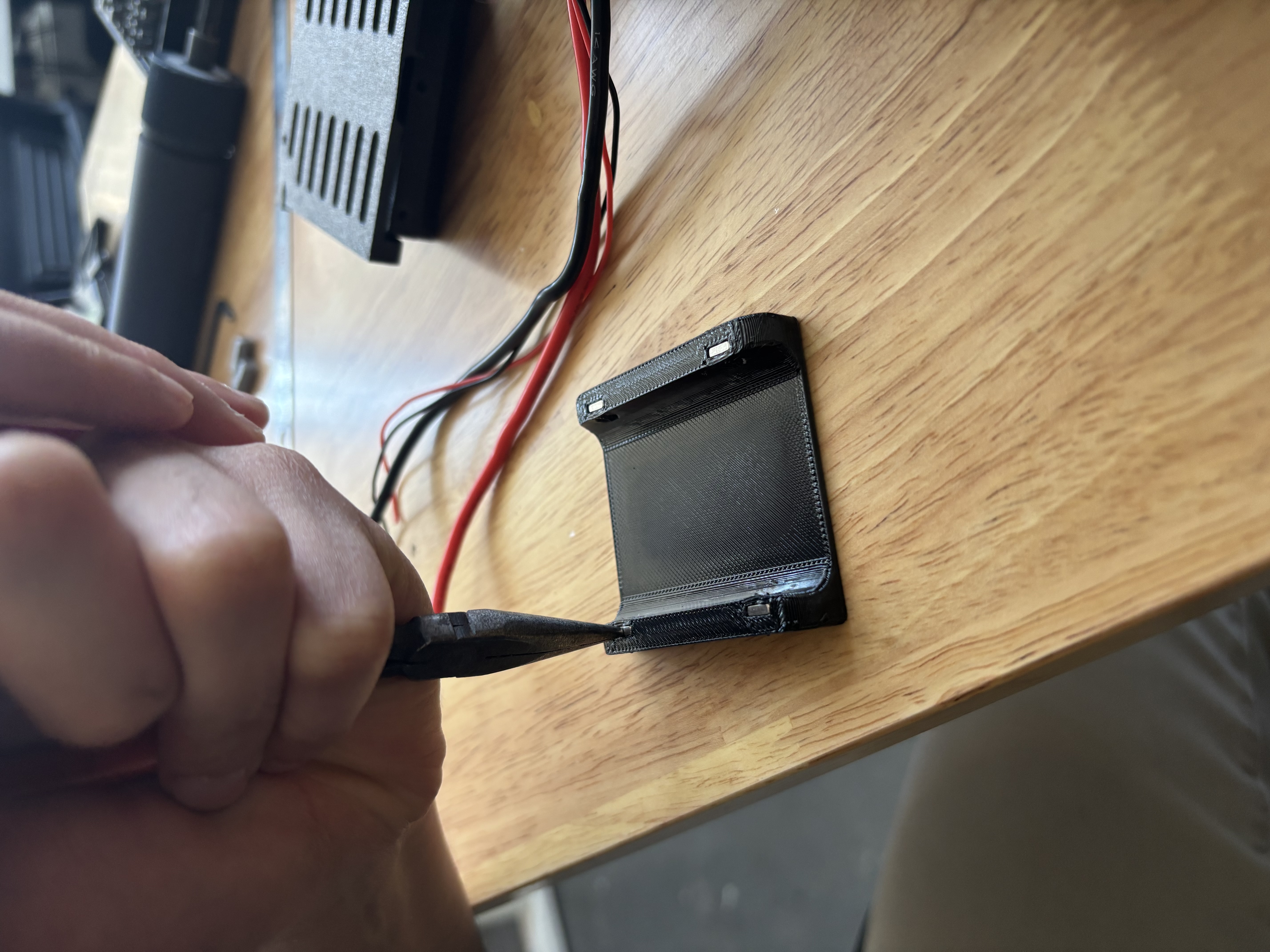
Install 36x NSQ-M3 in all the TPU (per pair). Use pliers to push them in.
edit step
Step 18
Fasten and Loctite all TPU with 36x BH-TX-M3-08 (per pair). Mark screws with white chalk. Make sure the wire is not tangled so the E2 TPU Cover Flat does not bulge.
edit step
+ Add step
Quality checklist
- E2 TPU Cover Flat does not bulge
- W0 Thick is flush with both sides of the W0 bracket
- Coupler is on the opposite side of the end stop tab
- All wires are coming out of the correct slots