Shoulder Assembly (S1 + S2)
Builds the shoulder/chest (stations S1 + S2): chest cover, bus bars, CAN board, X8 motors, and S2 brackets. Tools: RTV162 glue, M4/M3/M5 socket wrenches, T20 wrench, T10 wrench. Source: Notion – Axol Assembly Instructions (migrated 2026-07-14)
Parts used
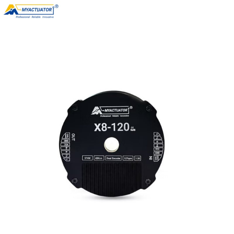 2× RMD-X8-120 Motor
 1× S1 Endstop Tab
 2× S2 Bracket
 2× S2 Bracket Support
 2× S2 Endstop
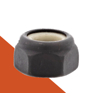 4× NNY-M4
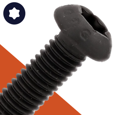 28× BH-TX-M4-16
 5× 22-16AWG M5 Ring Terminal
 4× 12-10AWG M5 Ring Terminal
 3× JST GH 2 Pin Pigtail
 1× Assorted Heatshrink
 1× RTV162
 1× Complete Chest Assembly
 2× S1 CAN -> S2 CAN Board Assembly
 2× SO-HX-M4-07-80-AL
Step 1
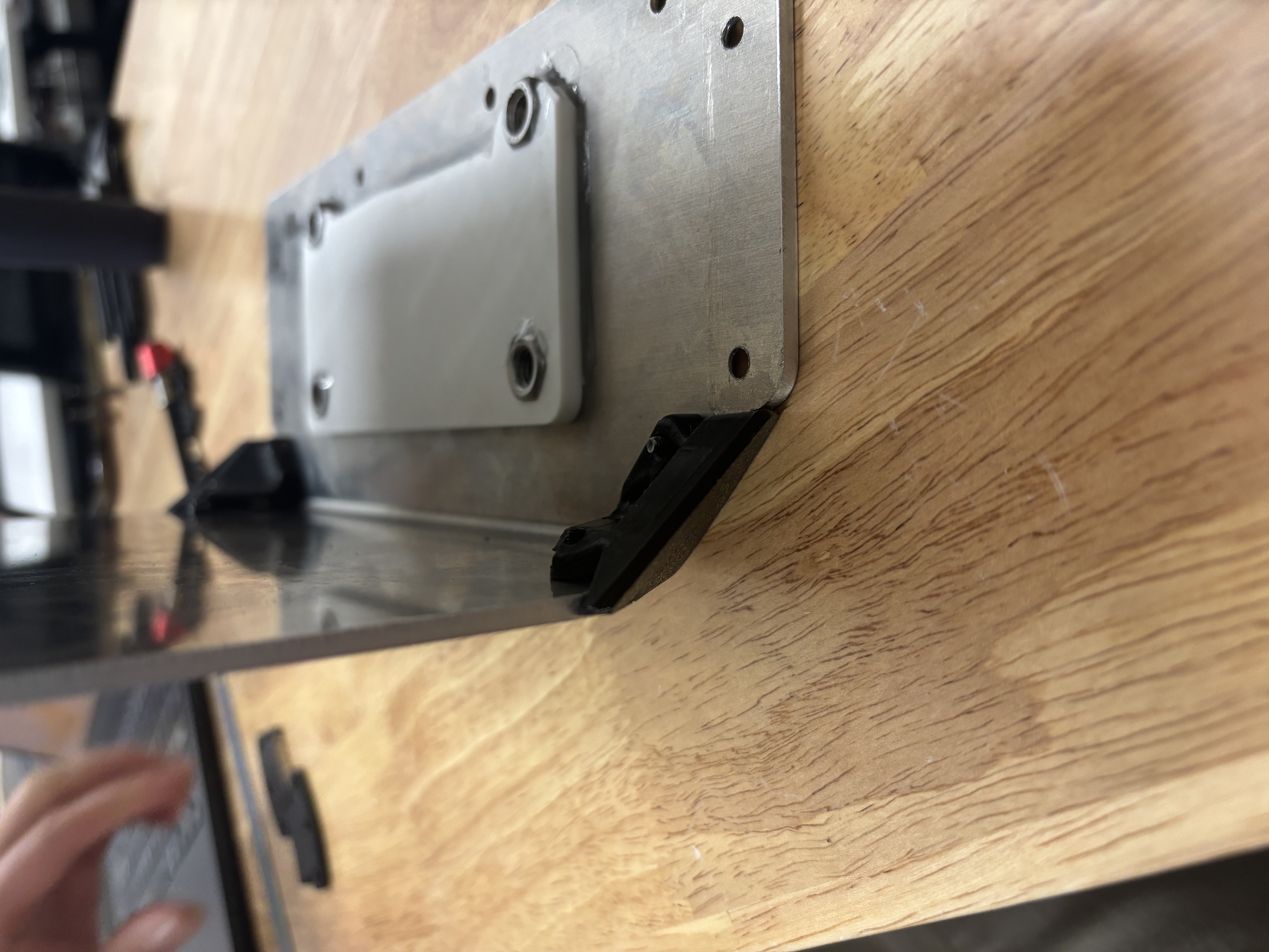
Fasten 1x S1 Corner Protector TPU Left and 1x S1 Corner Protector TPU Right to the S1 Chest Cover with 6x FH-TX-M3-10 and 6x NSQ-M3.
edit step
Step 2
Fasten 1x S1 Endstop Tab with 2x DP-R-03-06 and 3x BH-TX-M4-12.
edit step
Step 3
Fasten 1x XT90E-M Pigtail with 2x FH-TX-M3-10 and 2x NNY-M3.
edit step
Step 4
Install 2x NNY-M3 into the bus bar housing, flat side facing the little tab above it.
edit step
Step 5
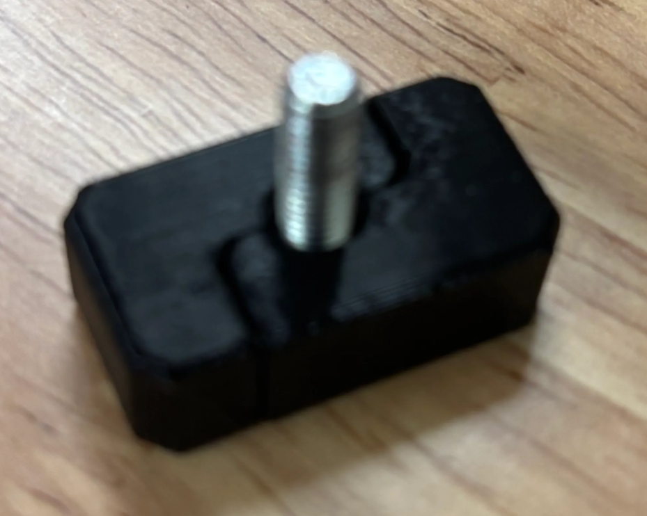
Install 1x HB-HX-M5-16 into the bus bar housing: place the bolt into the housing and press the housing together.
edit step
Step 6
Install 2x Bus Bars with 4x BH-TX-M3-10.
edit step
Step 7
Press 1x NNY-M2 into the back of the CAN Board Panel.
edit step
Step 8
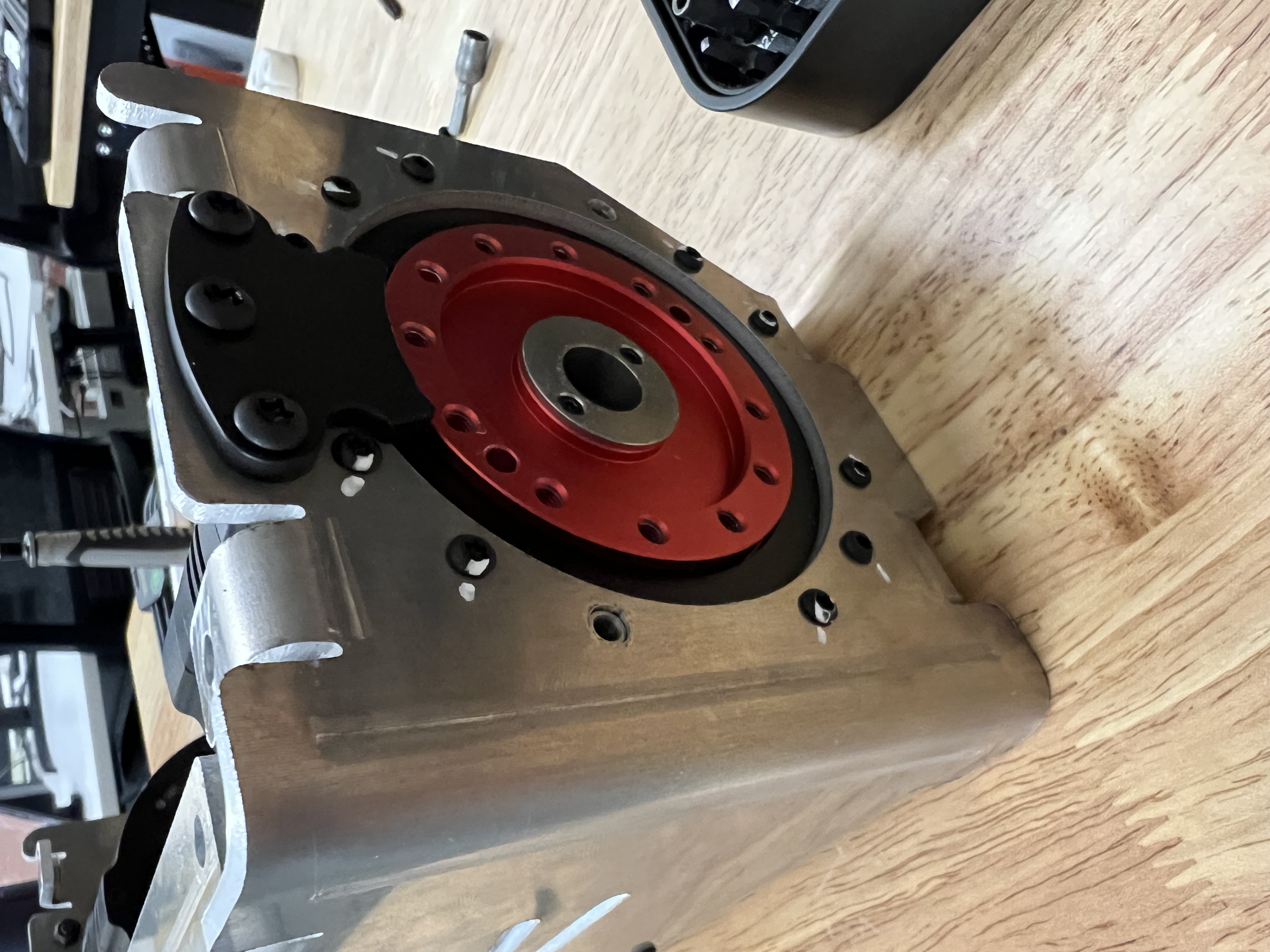
Install 2x RMD-X8-120 Motors with 22x BH-TX-M3-12.
edit step
Step 9
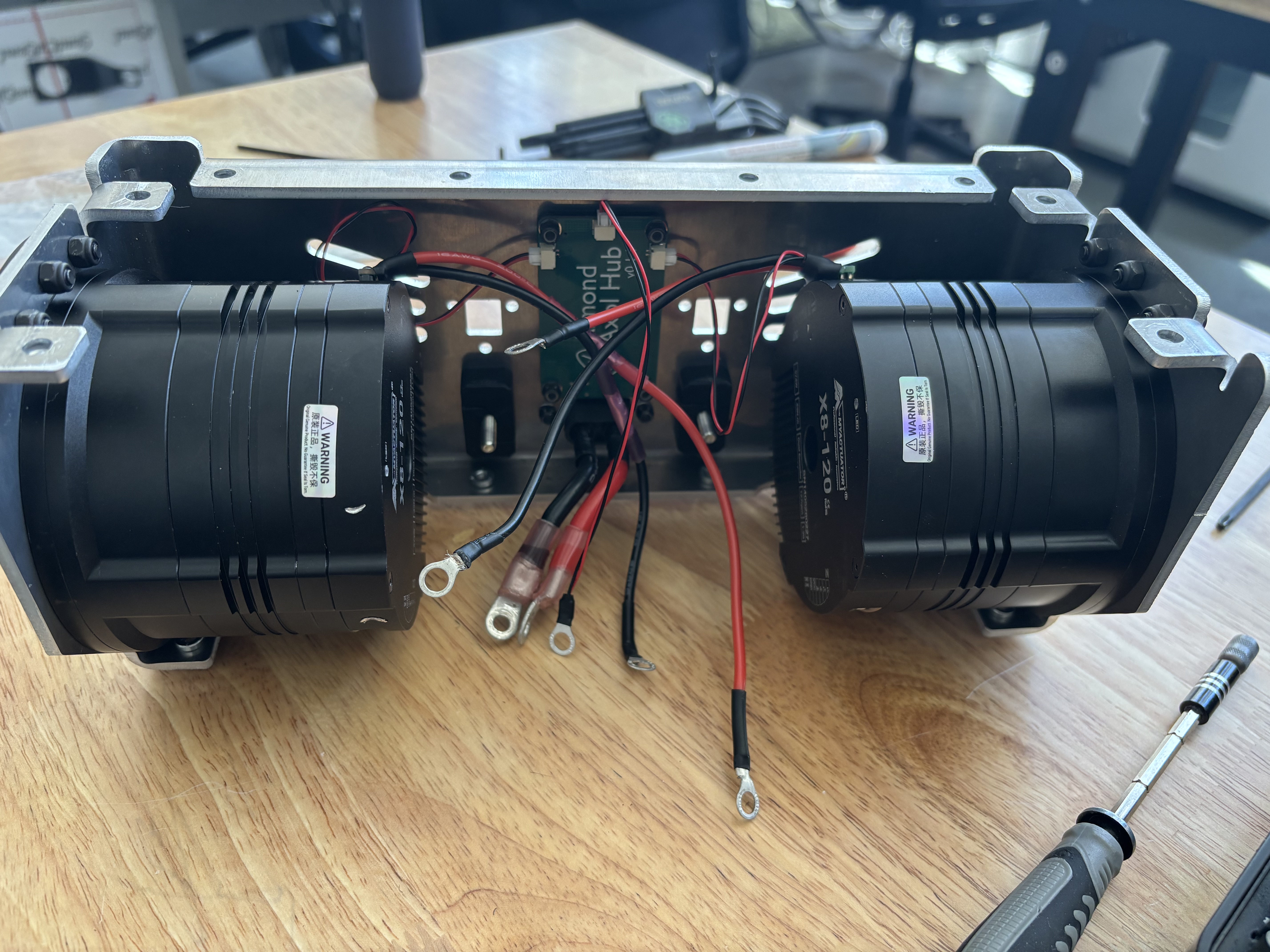
Install the CAN Board Panel on the back of S1 with 4x CAN Board Spacers, 4x NNY-M3, and 4x BH-TX-M3-12. Plug the JST into the CAN board, then fasten the CAN board to S1, then plug the XT30 into the motors and apply RTV162 glue.
edit step
Step 10
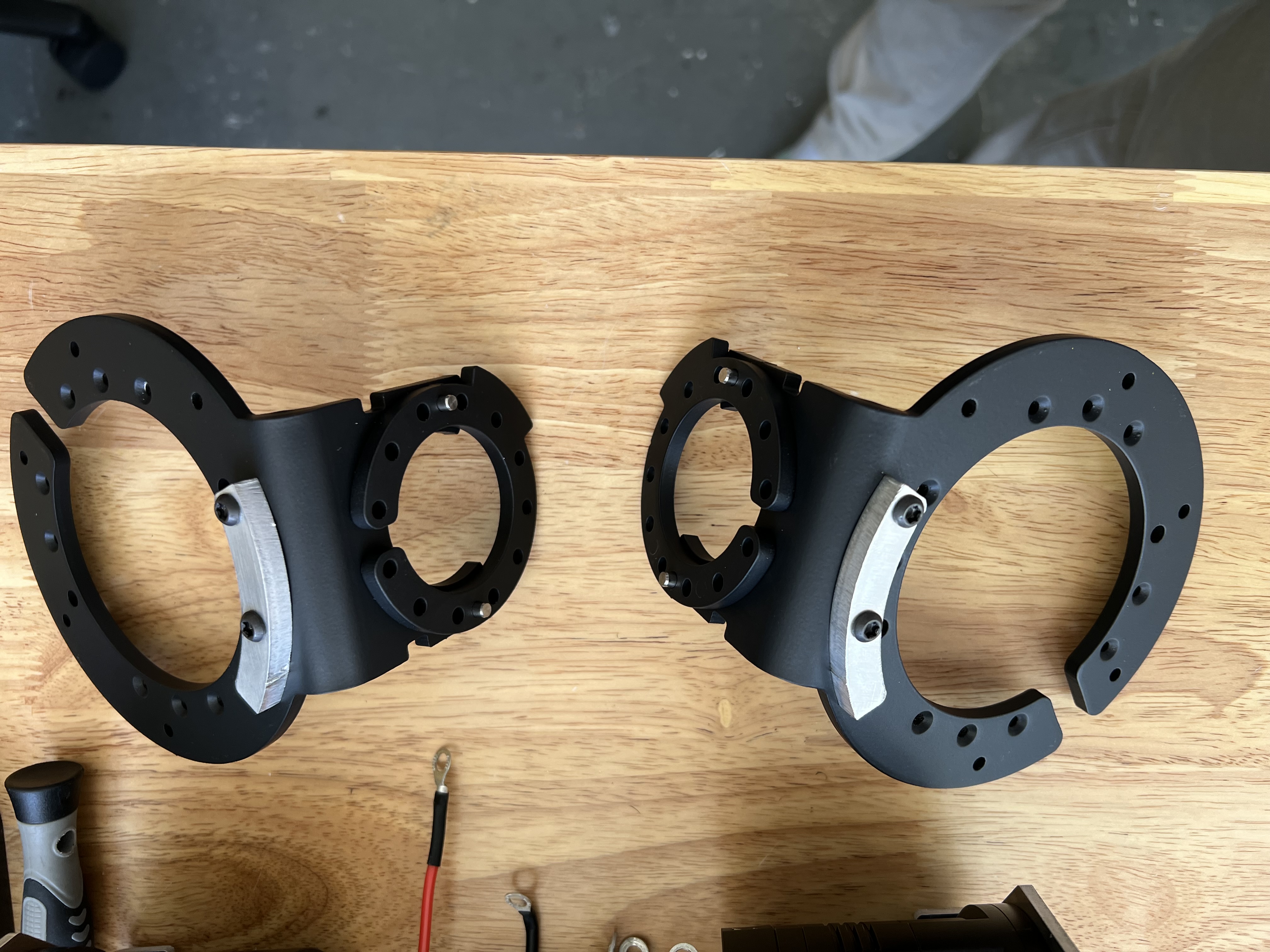
Install 1x S2 Endstop into the S2 bracket with 2x BH-TX-M4-16 and 2x NNY-M4. 2x DP-R-04-14, 2x DP-R-03-06. Tip(coupler should be face opposite and down of the end stop, end stop long side should be in the back of robot)
edit step
Step 11
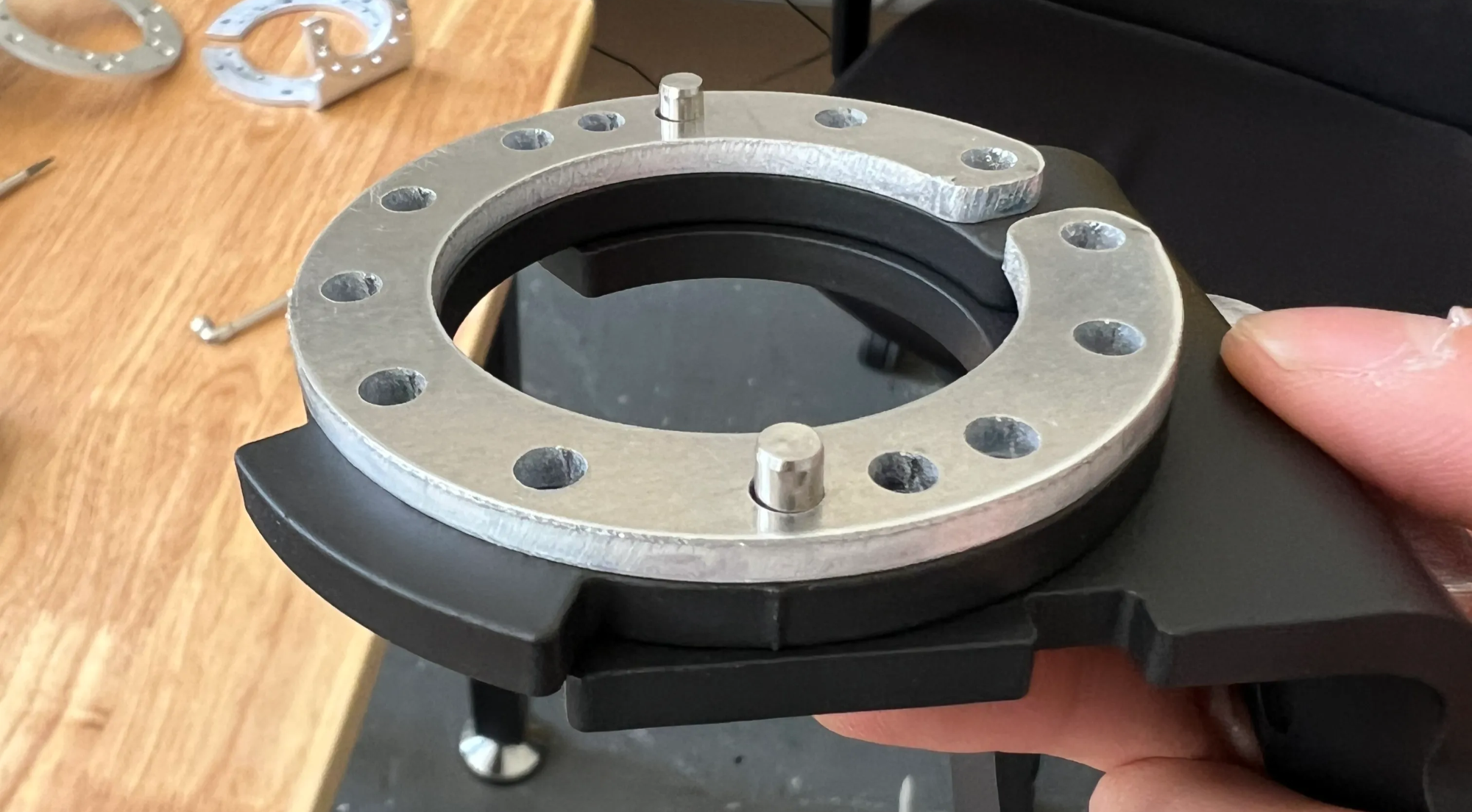
Press 1x S1 Coupler with Endstop 4.75mm into the S2 bracket, using the jig to attach the dowel pins.
edit step
Step 12
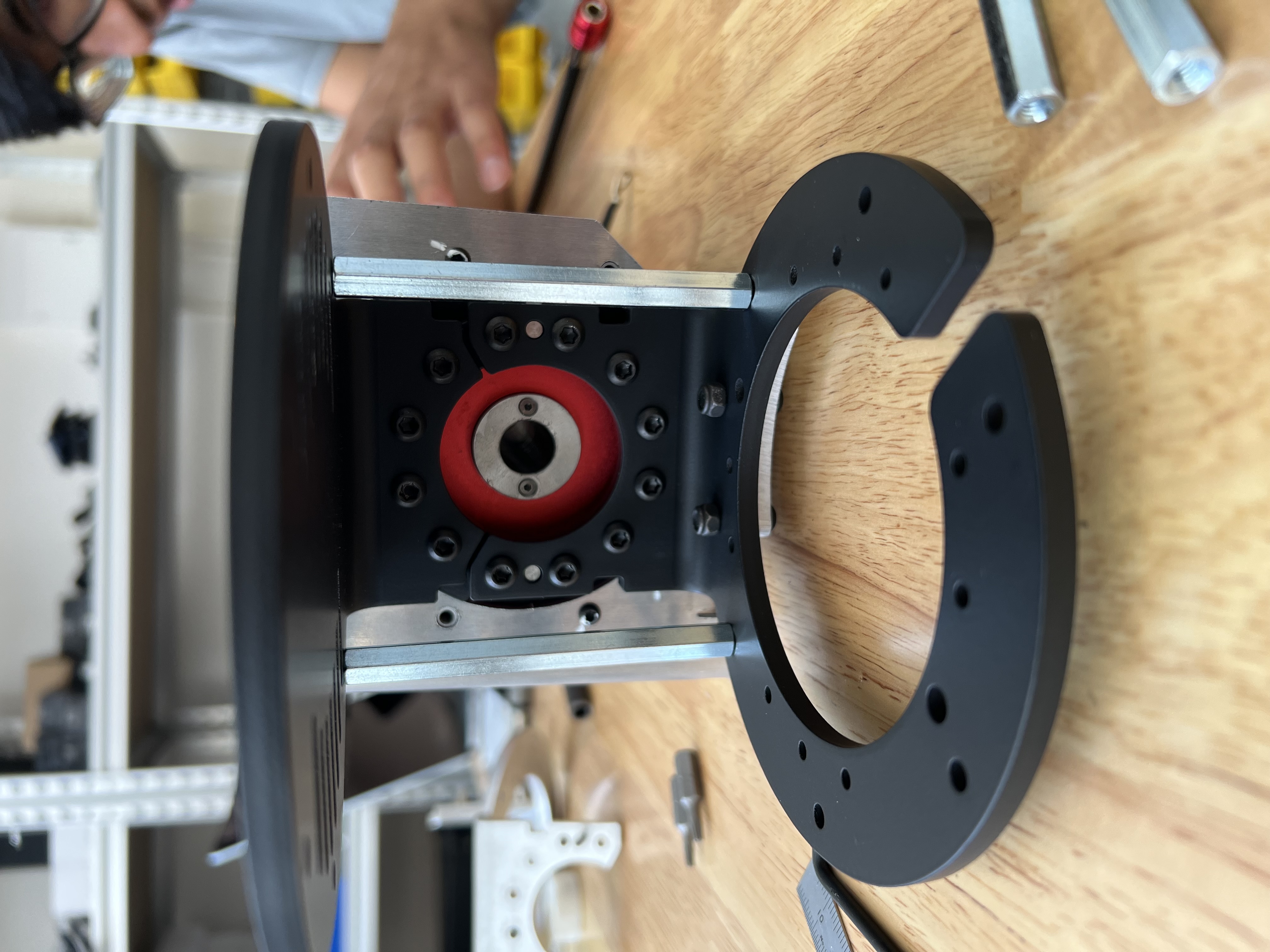
Fasten with Loctite the S2 brackets onto the S1 motor shaft with 12x BH-TX-M4-16. Use 2x SO-HX-M4-07-80-AL to make sure the screws are seated properly. Chalk the screws.
edit step
Step 13
Feed the S2 Cable through the S1 motor and attach CAN to the S1 CAN cable.
edit step
Step 14
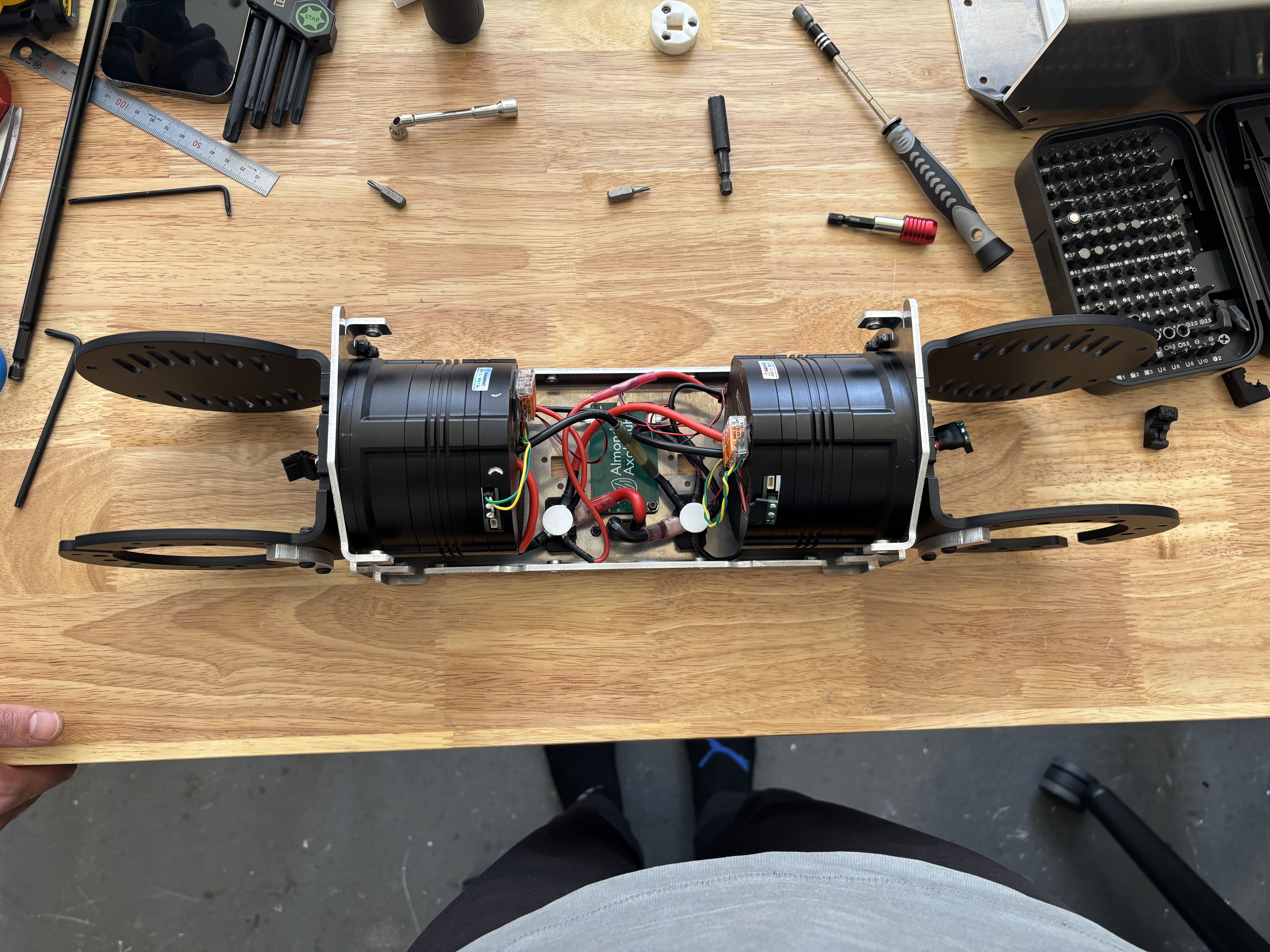
Attach the ring terminals to the power block. The red and black pigtails from the XT90E cross each other.
edit step
+ Add step
Quality checklist
- M4x16 for the S1 motor shaft are flush (they can bottom out)
- WAGO pull test
- JST pull test
- XT30 fully seated
- PWR on left, GND on right